Introduction
The Model A-13 Sunbeam Dry Iron was yet another device my grandma sent over to me for repair. Having seen the last device she sent over, her desk lamp, broken further rather than repaired, she was prepared to part with the iron when she gave it to me. My grandma had been using the iron since the 1970s and preferred how manageable it felt in her hand unlike the larger contemporary steam irons. However, recently she had noticed that the temperature control switch wasn't working correctly. The iron was always running hot even when the temperature adjustment knob was set to "off". This made it difficult to iron linens as one had to be careful not to burn the fabric. Unlike the lamp, this story is one of great success with the iron returned to full working condition.
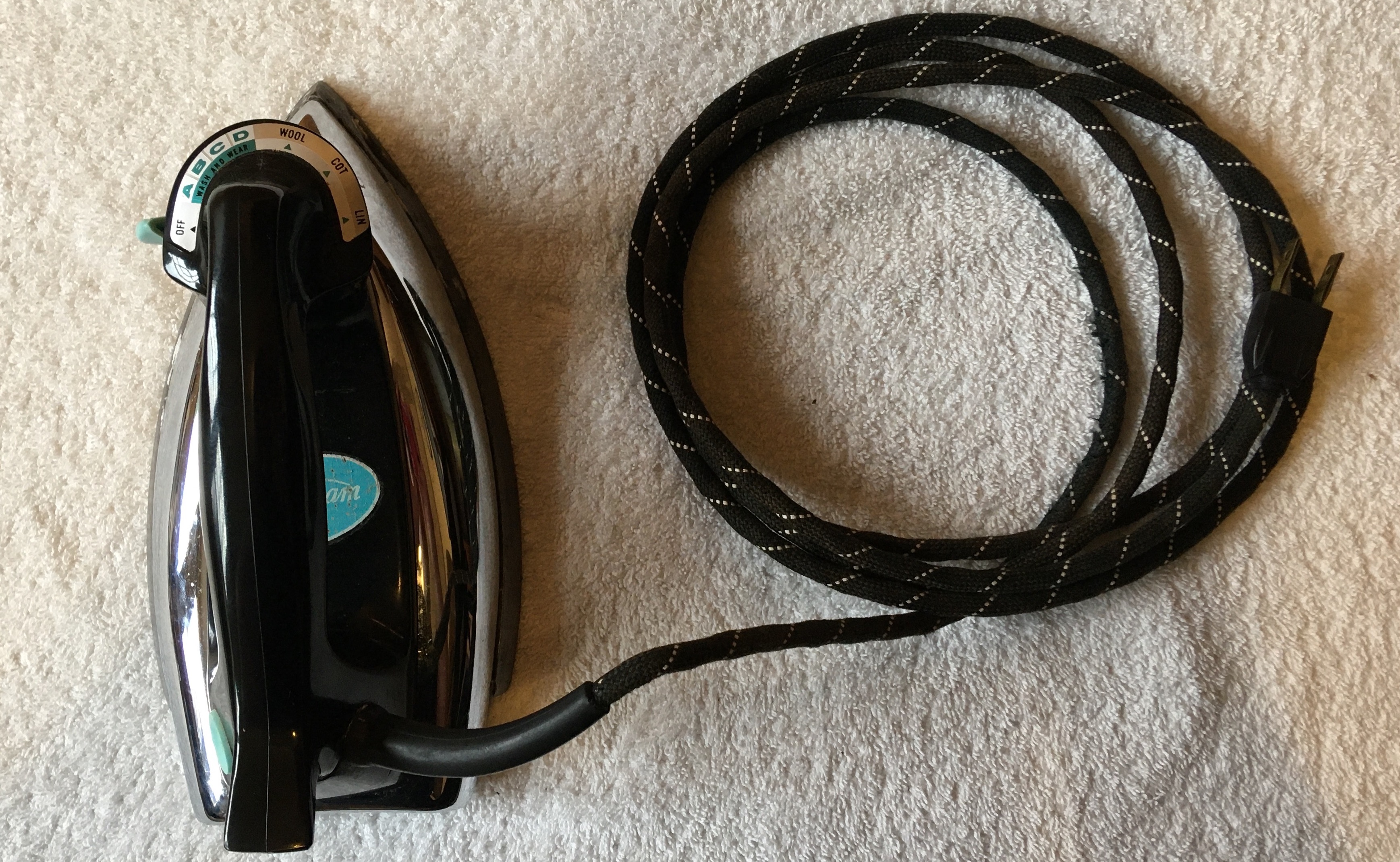
Original Iron
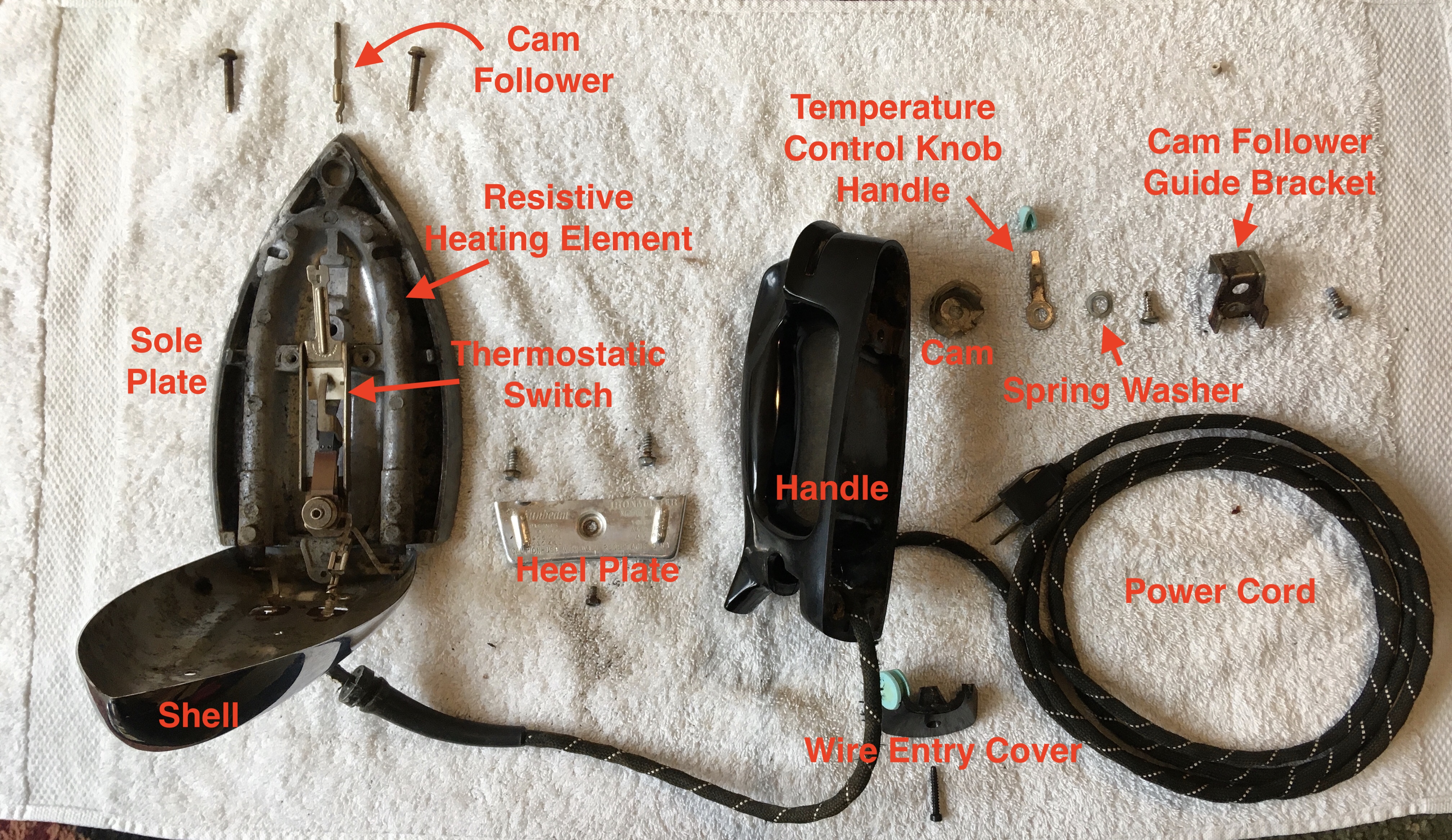
Labelled Exploded View
Compared to previous teardowns, the iron was one of the most challenging products I've disassembled. The fasteners securing components together were well hidden on the product and the handle, shell, and sole plate were connected together with a hidden press fit connection. As a result, the iron required careful inspection and prodding to disassemble it in a nondestructive manner. During this inspection, I noticed that the patent numbers for the iron were inscribed on the heel plate. Looking up the three patent numbers on the US Patent Database, each patent number had an associated patent document. Among these patent documents, only one discussed the dry iron model. Download the patent document here or read it below at the end of this webpage. The patent proved to be a useful resource in understanding how the iron worked and thus how its failures could be remedied.
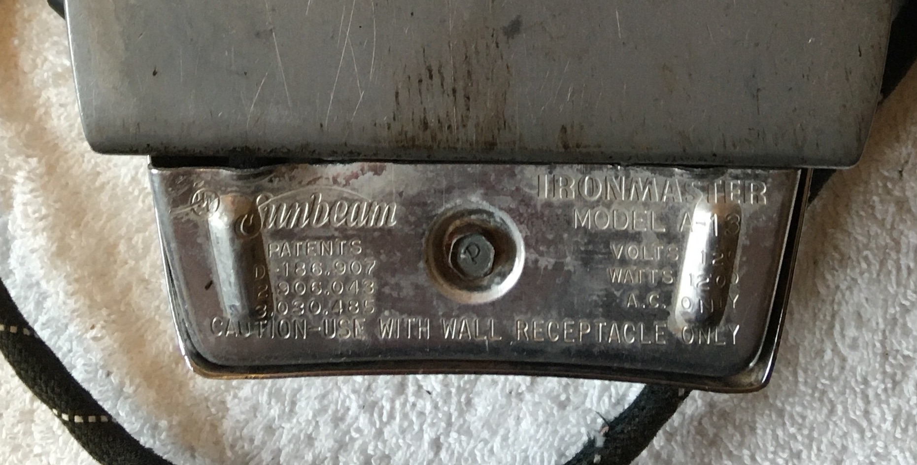
Patent Information on Heel Plate
Repairing the Thermostatic Switch
Since the iron's issue was one of temperature control, I examined the thermostat of the iron in great detail to find out what was wrong. When I initially looked at the temperature adjustment knob from the outside, I assumed the thermostat was as simple as just a potentiometer that acted as a variable resistor controlling the current supplied to the resisitve heating element. However, with the patent dated at 1962, this device was produced before the age of modern microelectronics. In fact, about the only electronic components were wires. The thermostat is almost completely mechanical. The mechanism has many moving parts, but with some study it can be understood and its beauty appreciated.
The mechanism begins with a cam, secured to the temperature control knob handle. As the temperature control knob handle is rotated by the user, the cam rotates internally. The cam is made of a circular piece of metal with a sloped ramp along its rim. Resting on this ramp is the head of the cam follower shaft. Rotating the cam causes the cam follower head to slide up or down on the ramp. Since it is prevented from rotating by several guiding holes, the cam follower is pushed down or allowed to rise. When the temperature control knob is initially on the "off" setting, the cam follower head rests at the bottom of the cam ramp and the cam follower is as high as possible. When the temperature control knob is turned, the cam follower head moves up the cam ramp and the cam follower is lowered.
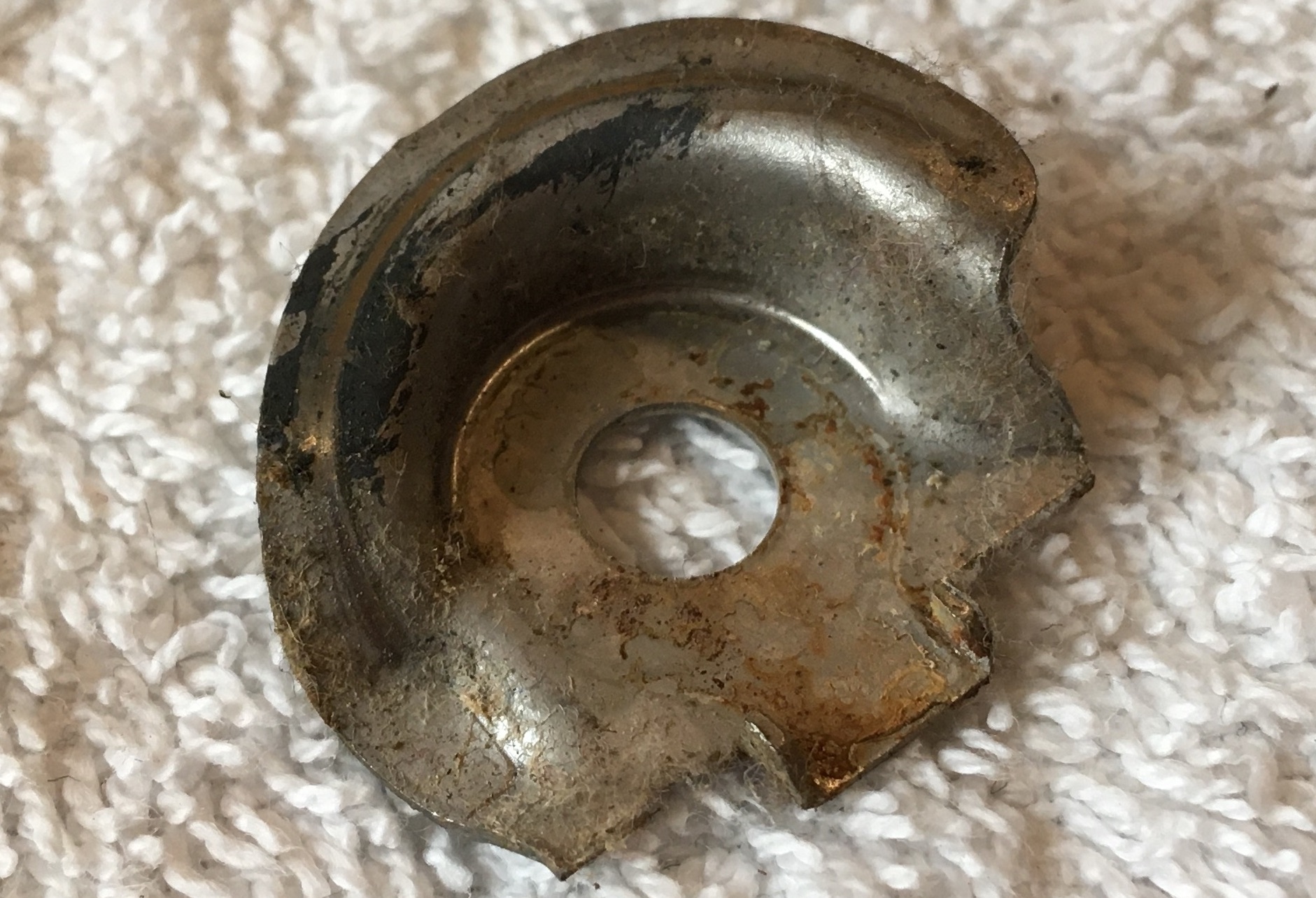
Cam
The cam follower connects to a lever on the thermostatic switch contained on the sole plate of the iron. As the temperature setting is turned up the cam follower presses down on the lever, lifting up an electrical contact and pressing it into another electrical contact. With the circuit connected, current begins flowing through the resistive heating element and the iron begins to heat. As the iron and also the electrical contacts heat though, a bimetal plate holding the upper electrical contact deflects upwards breaking the electrical contact and thereby preventing continuous heating. As the bimetal plate cools it returns to its original position, once again making electrical contact and heating the iron. Through this process of connecting and breaking the circuit, the temperature of the iron is approximately maintained at a certain level, hence the name thermostatic switch. When the cam follower presses down further on the lever, the lower electrical contact is lifted higher reducing the range over which the upper electrical contact has to deflect away from it. Consequently, the circuit remains connected longer, allowing more current to flow through the resistive heating element and the iron to get hotter.
The cam follower was intelligently designed as two separate shafts, with one threaded into the other. With this design, the thermostat setting could be adjusted by changing the length of the cam follower. Too well buried to be easily accessed by the everyday user, this adjustment was likely reserved for technicians at appliance servicing stores.
The thermal contacts are not easily visible on the thermostatic switch as they are hidden away on the bottom of the mechanism. Instead, the thermostatic switch components can be better visualized with the aid of the annotated cross-sectional drawings of the iron in the patent. Below is an image of the thermostatic switch as well as a video demonstrating the impact translation of the cam follower has on the mechanism. As the arm resting on the white insulated plate is lifted, it carries with it the lower electrical contact.
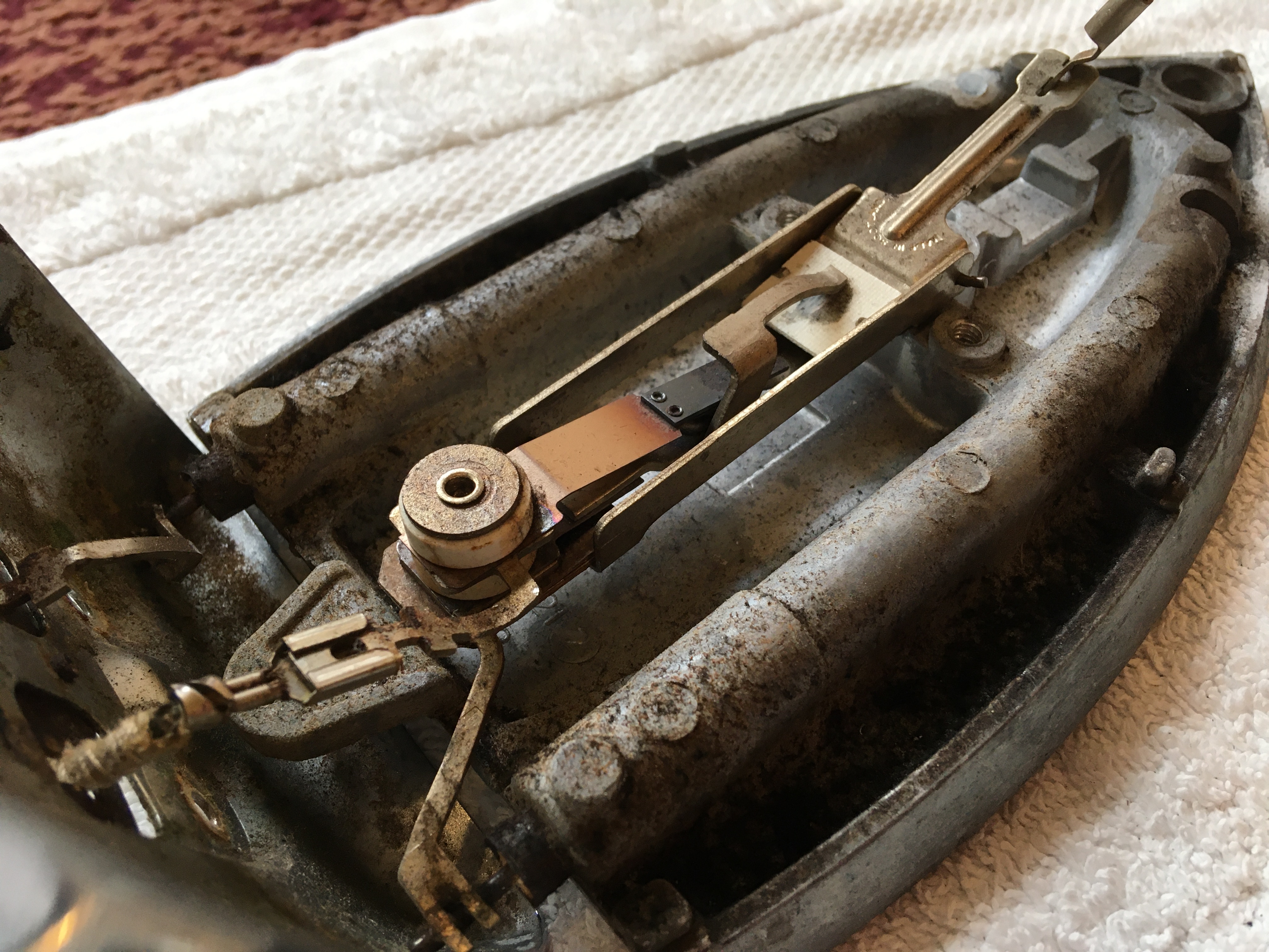
Thermostatic Switch
When the lower electrical contact is not being lifted up, the upper electrical contact rests on a small insulated pin-cap as opposed to sitting on the lower electrical contact. This ensures that the circuit is open until the temperature knob is rotated from the "off" setting. However, the insulated pin-cap had fallen off in my grandma's iron and instead the upper electrical contact rested on the metal pin where the insulated pin-cap should have been mounted. This metal-on-metal contact connected the circuit, causing the iron to heat up even when set to the "off" setting. The "fix" was as simple as just remounting the pin-cap on top of the pin. With that, the iron was ready to go back into operation. Below are pictures of the pin and pin-cap indicated using red arrows. It is interesting to note that the metal components of the thermostatic switch were made in Scotland. Seeing the words "Made In" on any manufactured product immediately makes me think "Made In China", but of course China was not the manufacturing giant it is now back in the 1960s.
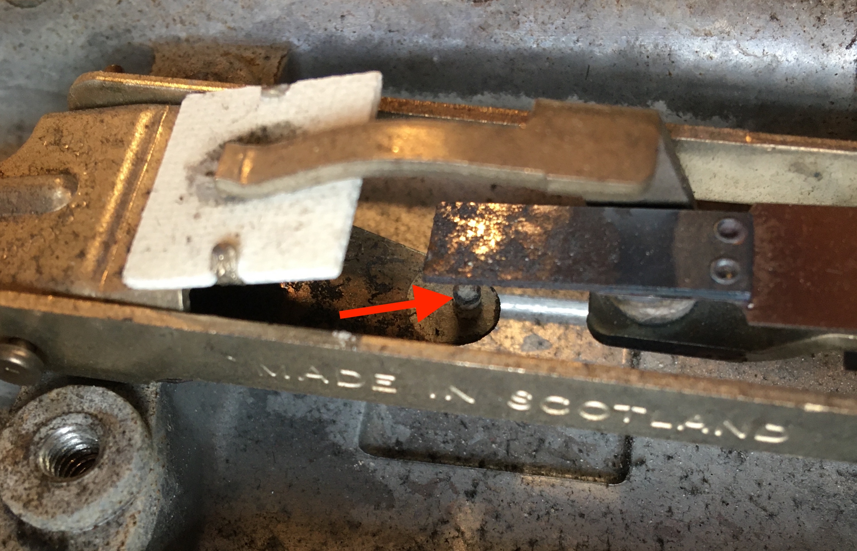
Metal Pin
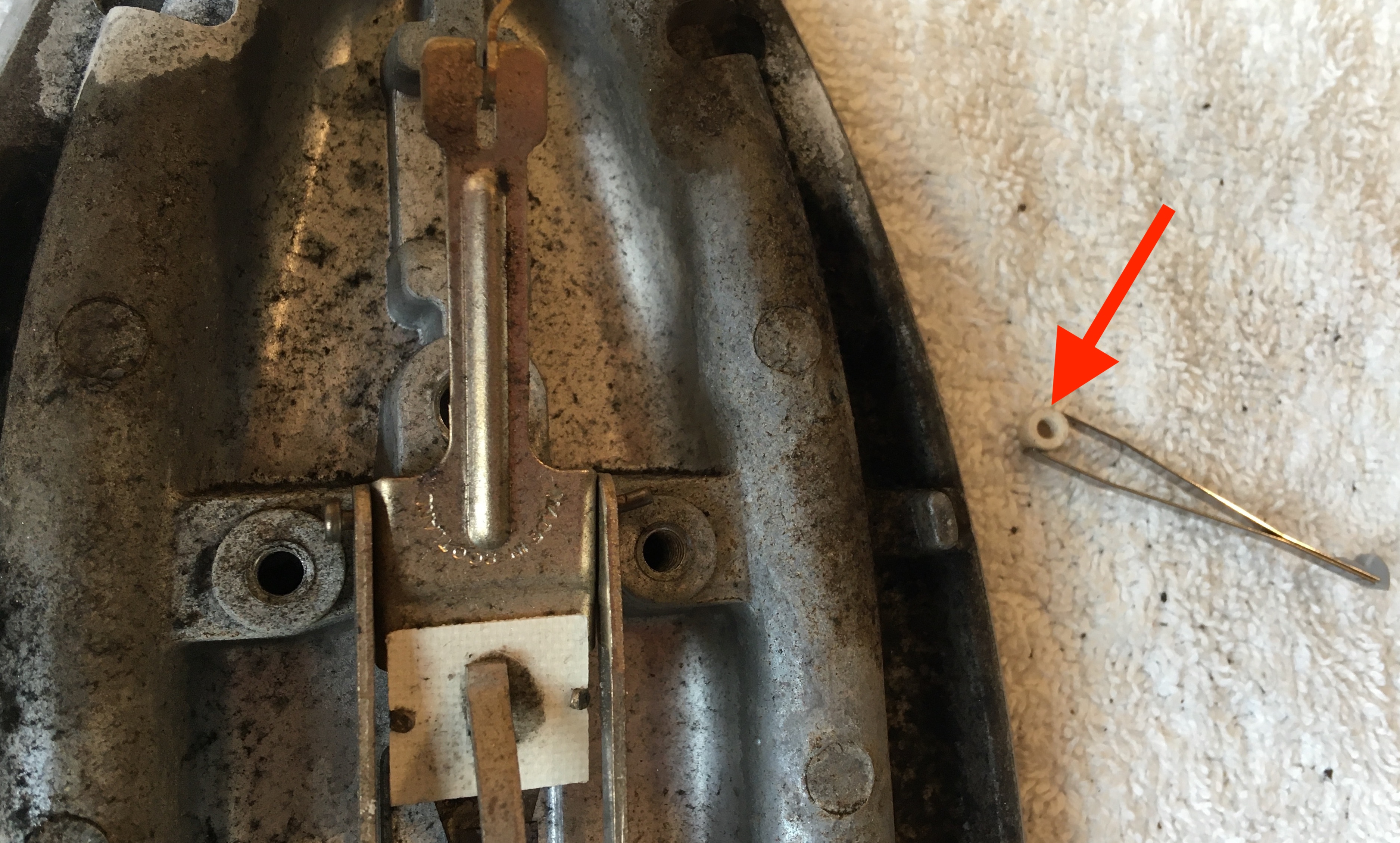
Insulated Pin-Cap
Fasteners
The fasteners used to secure the components of the iron were unlike those I had seen before. Of particular interest was a small spring washer used under the bolt securing the temperature control knob handle and cam. Given its warped appearance, the spring washer could have mistaken for a damaged flat washer. However, the warp in the washer is intentional as it allows energy to be stored when the washer is flattened under a bolt. The energy stored in the washer maintains the bolt in tension, engaging it tightly with the threads of a nut or other threaded hole. This reduces the impact vibrations can have in loosening a bolt, an important consideration for the temperature control knob which will experience a significant amount of movement.
Many of the bolts had flat hexagonal heads, required a nut driver to remove them. Although all the bolts are likely about the same age, they experienced different levels of corrosion based on their material and location in the assembly. Additionally, all of the bolts except for one appeared to have a triangular portion cut out of their tips. One potential explanation is that these screws were self-tapping. The fluted tip of the screw would enable it to cut out a threaded hole in the material as it was driven into place. Although these self-tapping screws would be more difficult to manufacture, they would greatly simplify the product assembly process.
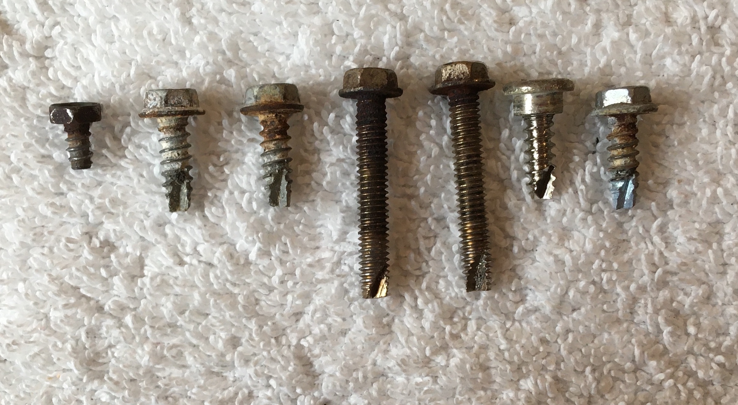
Bolts